This publication provides background information designed to accompany three objects in the Educational CAD Model Library: the Make to Learn Animation Machine (Bull & Gibson, 2023), a related Praxinoscope (Bull, 2023), and a variant developed by Elaine Wolfe (2024) . The CAD Library modules accompanying these objects enable students to recreate mechanical animation machines from the nineteenth century (Figure 1).
Figure 1
A Reconstructed Animation Machine

In the process, students learn about the way in which the human perception system interprets visual data. They also learn about the history of invention and innovation in the fields of animation and cinema.
Foundational Concepts
When a sequence of images is presented at a rate that exceeds 10 or 15 times per second, depending on the brightness of the images, the perceptual system no longer perceives each image individually. Animation occurs at rates on the threshold of human visual perception. The first silent movies were filmed at rates of 12 to 16 times per second. Modern film is projected at a rate of 24 frames per second. The standard for television adopted a rate of 30 images per second.
The rate at which a phenomenon — such as a sequence of projected images or the back-and-forth motion of a pendulum — is repeated in a given period of time is an important concept in science that appears in many contexts. Many of these contexts involve phenomena that are not visible. For example, waves occur in many media, including acoustic waves, electrical and electromagnetic waves, mechanical waves, light waves, and waves in water. Waves that occur in air, electrical circuits, or light waves cannot be seen. Consequently, while the concept of frequency is crucial to understanding of wave properties, these foundational but abstract concepts are difficult to master. When events occur at a rate that cannot be directly experienced by human senses, such as radio waves that occur at thousands or millions of times per second, an understanding of the phenomenon becomes more challenging.
Many scientific units are named in honor of famous scientists or inventors such as Heinrich Hertz. Scientific units like hertz, a term for “events per second,” are known as eponymous terms. Use of eponymous terms results in a derived meaning. If a phenomenon is described in events per second, the relationship to the phenomenon described is direct. When the same phenomenon is described using an eponymous term, the student must first remember that “Hz” is a derived term that means “events per second.”
An exploration of mechanical animation machines provides an opportunity to develop a solid understanding of the concept of “events per second” in a context that is visual and tangible.
Historical Animation Machines
Today’s cinema with high-definition digital video and surround sound is designed to provide an immersive moviegoing experience. It all began, though, with simple animation machines that were developed in the 19th century. A series of advances were inspired by the work that had gone before. Today’s modern cinema builds on the foundation of an invention that combined a magic lantern with a mechanical animation machine. The development and evolution of these mechanical animation machines is described next.
From earliest times, artists have told the story of their lives through paintings, and many of these paintings can still be seen on the walls of caves today. Over time artists began to create sequences of images to tell a story. Five thousand years ago an artist drew a series of images on a goblet (Figure 2).
Figure 2
An Ancient Artist Drew a Series of Scenes on a Goblet (Illustration by Alexis Jorgenson Based on Photograph by Salabin, 2010).
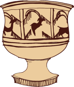
A series of scenes depicting a goat leaping up to eat the leaves on a bush can be seen as the goblet is turned. This early effort at depicting movement through a sequence of images captures the essential idea underlying animation.
Magic Disk
Skipping forward many centuries, the French inventor Joseph Plateau developed an animation device known as a magic disk (more formally called by the tongue-twisting name of phenakistiscope). The name is derived from a Greek phrase that can be translated as optical illusion.It consisted of a spinning disk with viewing slots in a stationary hub (Figure 3).
Figure 3
The Viewer on the Left Peers Through Slits in the Magic Disk to See an Animation of Galloping Horses Reflected in the Mirror on the Right.
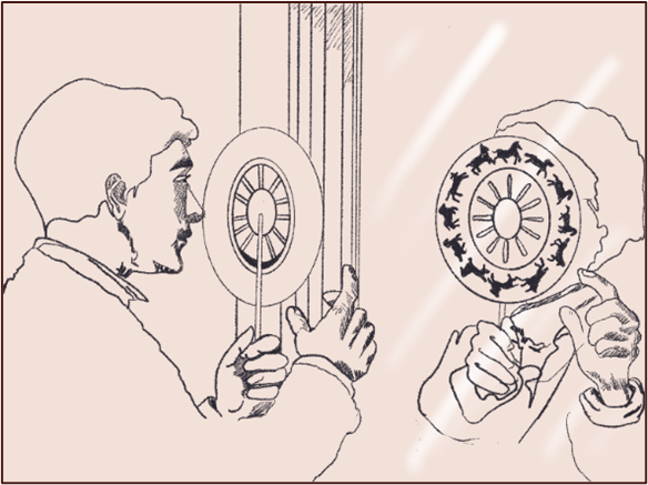
The viewer peered through the viewing slots to get a glimpse of each image in the animation as it moved past the slot. The slots in the magic disk expose each frame on the disk as it moves past a slot much as a film projector exposes the frames of a film one-by-one. When the images are seen at a rate of approximately 10-20 times per second, the illusion of motion occurs.
Zoetrope
Only one person at a time could view animations with Plateau’s magic disk. The British mathematician William George Horner was intrigued by the magic disk and developed an improved version, the animation cylinder (Figure 4). Horner used the term zoetrope to describe this device. An 1837 issue of the Philosophical Magazine and Journal of Science described Horner’s apparatus in the following manner: “The apparatus is a hollow cylinder with apertures at equal distances placed around the edge. Drawings on the interior surface will be visible through the opposite apertures.”
Figure 4
A Zeotrope Is an Optical Machine That Displays Animated Sequences
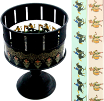
The board game maker Milton Bradley later manufactured and distributed the optical apparatus under the name zoetrope, meaning “circle of life.”
Praxinoscope
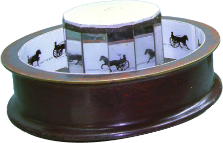
In 1877 the French inventor Charles-Emile Reynaud developed an improved version of the zoetrope, which he called a praxinoscope (praxis is the Greek word for “action”). It consisted of a series of mirrored segments that replace the viewing slits (Figure 5). The mirrored segments of the praxinoscope produce a brighter and less distorted animation than the zoetrope.
Figure 5
The Praxinoscope Was an Improved Animation Machine
Photographic Sequences
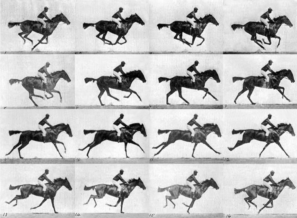
The earliest animated images were illustrated by hand, but in 1878 Leland Stanford hired the photographer Edward Muybridge to determine if all four legs of a galloping horse left the ground at the same time. Muybridge placed a sequence of cameras along a track to capture the motion of the horse. As the sequence in Figure 6 illustrates, all four legs of a galloping horse can simultaneously leave the ground. Muybridge placed strings on cameras at a racetrack. As a horse galloped through the strings, each string pulled a lever on a camera. This tripped the shutter of each camera and caused a series of pictures to be taken.
Figure 6
The First Animation Created by Combining a Sequence of Still Photographs (Muybridge, 1887)
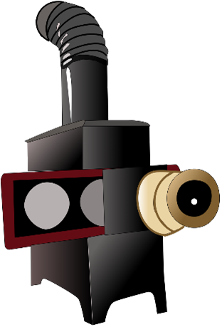
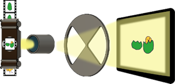
In subsequent years, Muybridge captured more than 100,000 images of animals, people, and objects in motion. He combined a zoetrope with a Magic Lantern to project the images. A Magic Lantern, invented by the Dutch scientist Huygens in 1659, used a mirror to reflect light off an object inside a box through a lens, projecting it onto a wall (Figure 7).
Figure 7
A Magic Lantern (Illustration by Alexis Jorgenson)
Muybridge called his invention, which combined an animation machine with a magic lantern, a zoepraxiscope. Muybridge presented the animated sequences that he captured to a paying audience in an exhibit hall at the 1893 Chicago World’s Fair. Today many of these animated sequences of frames are freely available on the Internet.
Magic Mirror Animation
Muybridge consulted Thomas Edison regarding the feasibility of combining his own animation machine with Edison’s phonograph to create synchronized sound and motion. Edison initially dismissed this idea as impractical for the technology of the time.
Figure 8
The Red Raven Magic Mirror
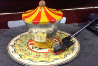
In the 20th century, however, the Red Raven record company achieved the goal of combining an animation machine with a phonograph record (Figure 8). Pictures on a phonograph record were reflected onto the mirrored segments of a praxinoscope as the phonograph turned. This popular toy was widely sold in the 1950s.
The Birth of Cinema
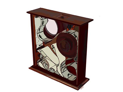
The meeting between Muybridge and Edison did not result in development of an invention that combined a phonograph with an animation machine as Muybridge had hoped. However, Edison was later inspired to invent the kinetosocope, which pulled a sequence of pictures on a strip of paper past a viewing window (Figure 9). This kinetoscope subsequently led to the invention of cinema as we know it today.
Figure 9
Edison’s Kinetoscope Created Animations by Displaying a Series of Pictures on a Strip of Paper (Illustration by Alexis Jorgensen)
Reconstructing Animation Machines
With appropriate scaffolding, a middle school student can use files in the CAD Library to reconstruct an animation machine.
Make to Learn Animation Machine
To provide scaffolding, a basic animation machine was developed in the Make to Learn Laboratory at the University of Virginia. This mechanism consists of a rotating disk with openings that are used to view a sequence of images on a strip that is pulled past the disk (Figure 10). Persistence of vision creates the illusion of motion.
Figure 10
The Make to Learn Animation Machine
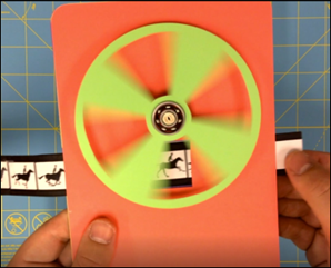
The mechanism can be constructed from card stock that is cut out with scissors or fabricated with a die cutter or a laser cutter, if one is available. A historical sequence of images such as the Muybridge horses can be used for the animated sequence, or students can use stop-motion photography to create their own animations.
An ancillary computer simulation that can be accessed through the CAD Library reconstructs the same elements in a digital format (Figure 11). This makes it possible to add a coding component that illustrates the way in which a physical activity can be emulated in a digital environment.
Figure 11
The Make to Learn Computer Simulation
Reconstructing a Praxinoscope
The Make to Learn Animation Machine (Figure 12) provides scaffolding for reconstruction of a 19th-century animation machine, the praxinoscope.
Figure 12
A Praxinoscope
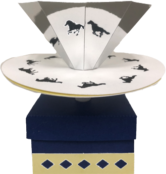
This mechanism is constructed from folded card stock. An octagonal cone is constructed from card stock with a reflective surface. As the cone rotates, images on a circular disk below the cone are reflected in the mirrored surface.
Construction of this mechanism requires greater manual dexterity than construction of the basic Make to Learn Animation Machine, but fabrication and assembly is within the capacity of a middle school student with sufficient scaffolding provided through associated instructional materials in the CAD Library.
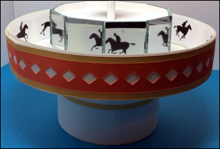
The activities that accompany the Make to Learn Animation Machine and the praxinoscope in the CAD Library are designed to serve as a springboard for recreation of other designs and inventions. Elaine Wolfe, a retired mathematics teacher, developed another variation of the praxinoscope (Wolfe, 2024) shown in Figure 13. This variation makes use of small mirrors acquired from a local craft store to serve as reflective surfaces.
Figure 13
Another Approach to Designing a Praxinoscope
Classroom Implementation
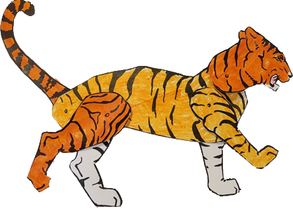
The animation activities were piloted in undergraduate classes at the University of Virginia and in engineering classes at Buford Middle School in Charlottesville, Virginia. The completed modules were then implemented in the classroom of Debra Shapiro, middle-school teacher in Suffolk, Virginia. Her students used designs from a book of jointed toy patterns (Cleaveland, 1918) to construct jointed figures connected with brads (Figure 14).
Figure 14
Constructing an Articulated Figure for Stop-Motion Animation
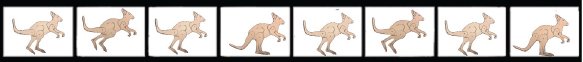
The articulated figures were posed in different positions. The posed figure were then used to reconstruct the real-life motion of the animal (Figure 15). The students used the cameras in their Chromebook computers to capture the sequences of images (Figure 16). The animation strips created in this manner (Figure 17) were then used to create the digital simulations and physical animation machines.
Figure 15
Reconstructing Real-life Motion Using Articulated Figures

Figure 16
Creating an Animated Sequence Through Stop-Motion Photography
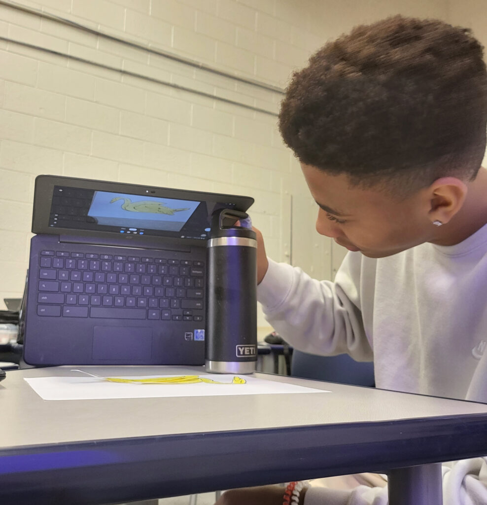
Figure 17
An Animation Strip Developed for the Animation Machine
These activities were implemented in a 6-week Exploratorium, in which the classes met for a total of 15 one-hour periods. All of the students in eight different classes of varying abilities were able to successfully implement the activity. Students reconstructed methods used by historic inventors to create animations. In the process, they learned about the underlying principles of animation and discovered that the historic concepts are equally applicable to modern-day digital animations. They also learned a variety of engineering and design skills aligned with the International Technology and Engineering Educators Association (ITEEA) standards.
One of the students, Kyler, developed an innovative method for implementing stop-motion photography using Chromebooks. Kyler was recognized by his school for this innovation and subsequently received an entrepreneur’s award related to photography. The revised activities were then incorporated into the ITEEA Engineering by Design curriculum. The activities were also published in the Educational CAD Model Library in open-source format, where they are freely available for anyone to use or modify in educational settings.
Summary
The history of the inventions described here illustrates the way in which innovations build upon one another. Huygens invented the Magic Lantern in the 17th century. By the beginning of the 19th century, advances in mass manufacturing led to the production of thousands of Magic Lanterns. This established the foundation for widespread storytelling through illuminated images.
The addition of animation extended these storytelling capabilities. The process of innovation and invention in the field of animation can be characterized in the following way:
- Advances evolved slowly over periods that spanned decades or centuries.
- Each advance was inspired by and built upon the foundation of prior inventions.
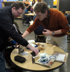
There is not a single final design. Instead, the initial reconstruction of a praxinoscope serves as an inspiration for a number of parallel designs. The activity can also be implemented in informal learning settings. Tim Pula, interpretive coordinator at the Smithsonian’s Spark!Lab, collaborated on an adaptation of the animation machine designed for museum settings.
Figure 18
Adapting the Activity for Implementation in an Informal Learning Setting
The animation activities that accompany the animation machines in the CAD Library are intended to provide scaffolding for initial exploration. The actual implementation will be different in each educational setting depending on the context and instructional goals.
Author Notes
Glen Bull is a professor in the School of Education and Human Development at the University of Virginia. Jo Watts is manager of the Make to Learn Laboratory at the University of Virginia. Rachel Gibson is an engineering teacher at Charlottesville High School in Charlottesville, Virginia. Ryan Novitski is the International Technology and Engineering Educators Association STEM Center for Teaching and Learning Director. Debra Shapiro is a technology and engineering teacher at Forest Glen Middle School in Suffolk, Virginia. Elaine Wolfe is a retired mathematics teacher in Fairfax, Virginia.
References
Bull, G. & Gibson, R. (2023). Animation Machine [Educational object]. Engineering CAD Library. NTLS Coalition, UVA Dataverse. doi:10.18130/V3/USY827
Bull, G. (2023). Praxinoscope [Educational object]. Educational CAD Model Library. Engineering CAD Library. NTLS Coalition, UVA Dataverse. doi:10.18130/V3/1U0E4N
Cleaveland, B. (1918). Jointed toy patterns: For coloring, cut out, and construction work. F.A. Owen Publishing Company.
Muybridge, E.J. (1887). Plate No. 626. Gallop, thoroughbred bay mare, Annie G. [Collotype]. National Gallery of Art. Accession No. 2006.133.101. https://www.nga.gov/collection/art-object-page.136536.html
Sałaban, M. (2010). Animation of pottery vessel found in Shahr-i Sokhta, Iran. Late half of 3rd Millennium B.C. https://commons.wikimedia.org/wiki/File:Animation_vase_2.jpg#file
Tissandier, G. (1884). Les récréations scientifiques, Internet Archive. https://archive.org/details/lesrecreationssc00tiss
Wolfe, E. (2024). The Reynaud praxinoscope [Educational object]. Engineering CAD Library. NTLS Coalition, UVA Dataverse. doi.org/10.18130/V3/T2OODG
![]()