A rotary motor is the traditional starting point for construction of an electric motor in school. However, the design for a rotary motor requires a mechanical commutator to reverse the polarity of the current each half turn of the motor. In practice, construction of a reliable commutator is mechanically complex and challenging to understand from a theoretical perspective.
This paper describes an alternative learning approach that uses the linear motor as a starting point for introducing related electricity and magnetism concepts. Once students understand the foundational principles of operation, they can then attempt design and construction of a rotary motor in a subsequent design. Computer-Assisted Design (CAD) files, instructional videos, and other instructional resources related to the linear motor described here are available in an associated Educational CAD Model Repository via the following link: https://github.com/maketolearn/Invention-Labs/tree/main/Linear%20Motor%20Lab
The Linear Motor Invention Kit that is the basis for this approach consists of a series of mechanisms and activities centered around a reconstruction of the Charles Page Electromagnetic Engine patented in 1854. This work was undertaken in the Make to Learn Laboratory at the University of Virginia in consultation with the curators at the Smithsonian’s National Museum of American History (Bull, 2014). The original patent model in the collections of the Smithsonian Institution was used as a reference for modern-day reconstructions (Figure 1).
Figure 1
Patent Model for the Charles Page Electromagnetic Engine
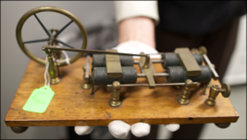
During the 19th century, exploding steam boilers in railway locomotives were a recurring hazard. Charles Page worked at the US Patent and Trademark Office and believed that electric motors could be used to make transportation safer. Page patented what he termed an electromagnetic engine, which today can be described as a linear motor (since the armature of the motor moves back and forth in a straight line). Two electromagnets on one side of the motor pull an iron armature toward the electromagnets, turning a flywheel that switches power to another set of electromagnets on the opposite side, causing the motor to move back and forth. Some reconstructions incorporate all mechanical features of the original design, including a flywheel and commutator (Figure 2).
Figure 2
Reconstruction of the Charles Page Engine
The linear motor models discussed in this article are designs that have been updated for use with contemporary electronic and computer controls.
Goals, Standards, and Concepts
The mission of the Smithsonian’s National Museum of American History (n.d.) is “to help people understand the past in order to make sense of the present and shape a more humane future” (para. 8). Development of a laboratory reinterpreting the Charles Page Linear Motor using modern-day technologies was undertaken in fulfillment of that mission.
The goals of this unit are to construct a linear motor, control a linear motor manually or by using an oscilloscope or microcontroller through activities that demonstrate the principles of electricity and magnetism, and incorporate the motor into a separate, custom mechanism. An exploration of historical and modern linear motors provides a context for helping students understand the science, mathematics, and engineering principles that underlie this transformational invention (Bull et al., 2015, 2016).
The unit can be used to address Standards for Technological and Engineering Literacy (International Technology and Engineering Educators Association, 2020), the Next Generation Science Standards (NGSS Lead States 2013), the Principles and Standards for School Mathematics (National Council of Teachers of Mathematics, 2000), and Common Core State Standards (National Governors Association Center for Best Practices & Council of Chief State School Officers, 2010)
The Standards for Technological and Engineering Literacy
STEL 6D. Engage in a research and development process to simulatehow inventions and innovations have evolved through systematic tests and refinements.
Next Generation Science Standards
MS-PS2-3 Motion and Stability: Forces and Interactions
Ask questions about data to determine the factors that affect the strength of electric and magnetic forces. [Clarification Statement: Examples of devices that use electric and magnetic forces could include electromagnets, electric motors, or generators.]
- HS-PS2-5 Motion and Stability: Forces and Interactions
Plan and conduct an investigation to provide evidence that an electric current can produce a magnetic field.
- MS.ETS1-4 Engineering Design
Develop a model to generate data for iterative testing and modification of a proposed object, tool, or process such that an optimal design can be achieved.
Common Core State Standards (Mathematics)
Extension activities involving solenoids can be used to address the following mathematics standards.
Grade 8.F.4: Use functions to model relationships between quantities.
4. Construct a function to model a linear relationship between two quantities.
Algebra A-CED: Create equations that describe numbers or relationships
1. Create equations and inequalities in one variable and use them to solve problems. Include equations arising from linear and quadratic functions, and simple rational and exponential functions.
2. Create equations in two or more variables to represent relationships between quantities; graph equations on coordinate axes with labels and scales.
4. Rearrange formulas to highlight a quantity of interest, using the same reasoning as in solving equations.
Several key concepts are introduced in the unit:
- Magnets have a polarity that causes one magnet to attract or repel a second magnet.
- The polarity of one magnet can be used to control the movement of a second magnet.
- A wire carrying an electric current has a magnetic field surrounding it. A coil of wire carrying an electric current will create a magnetic field similar to that of a permanent magnet.
- The control magnet that moves the second magnet can either be a permanent magnet or an electromagnet.
- A battery also has a positive and negative terminal.
- Reversing the connections to a battery in a circuit in which current is flowing through a coil of wire (solenoid) also changes the polarity of the electromagnet.
- The events per time period in this scenario refers to the number of times the polarity of the electromagnet changes in a given time period, causing a corresponding number of back-and-forth movements of the linear motor.
Educational Models
Two linear motor models developed to help students understand the underlying principles and operation of linear motors are described in the following sections. Students are expected to use these prototype models as a starting point for designing their own linear motor. These models were piloted in middle school classrooms, but also have been used at the high school level and in a community college course.
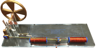
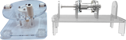
Visible Linear Motor
The Visible Linear Motor (Figure 3) enables all the components to be seen, enabling students to understand its operation. This version has the lowest part count of any linear motor model, making it easier to fabricate and construct (Bull et al., 2018). Fabrication details are provided in the Educational CAD Model Repository.
Figure 3
Visible Linear Motor
This implementation of the linear motor uses an electronic oscillator rather than a mechanical flywheel (such as the flywheel shown in Figure 2) to change the polarity of the solenoid and drive the armature back and forth. This version of the linear motor has several advantages compared with 19th-century designs:
- It has fewer components and, therefore, takes less class time to fabricate and construct.
- Because there are fewer components, this design is more robust and more reliable.
- Because there are fewer components, students can more readily understand the principles of operation.
- This design also lends itself to operation using electronic and computer controls providing an entry point to computer programming and microcontrollers.
One of the chief limitations of this design is that it is best suited to operation in either a fully horizontal or fully vertical position, which constrains the range of design possibilities for mechanisms that incorporate this version of the linear motor.
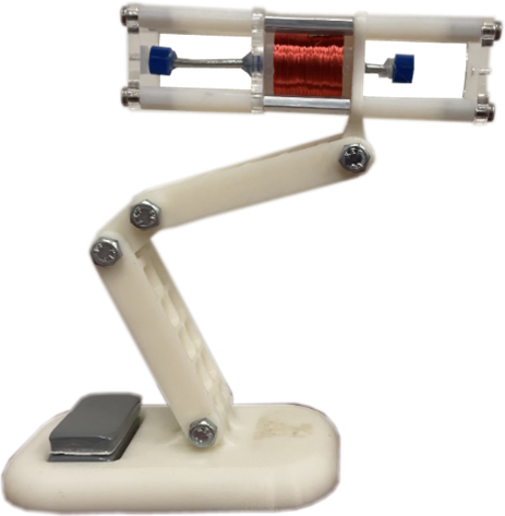
Adjustable Linear Motor
The Adjustable Linear Motor enables the motor to be operated in any orientation (Figure 4). This flexibility increases the range of design possibilities for mechanisms that incorporate the linear motor. However, this increased flexibility comes at the cost of added complexity. Additional components require more time to fabricate and source. This design also takes longer to assemble. When students can see the tradeoffs in different designs, it helps them understand how a design can be optimized for a specified outcome.
Figure 4
Adjustable Linear Motor
Fabrication and Assembly Directions
Detailed instructions for fabricating and assembling both versions of the linear motor are available in the Educational CAD Model Repository online at https://github.com/maketolearn/Invention-Kits/tree/main/Linear%20Motor%20Kit. The repository files are hosted as a subdirectory in GitHub (Figure 5).
Figure 5
Linear Motor Kit Fabrication Files
The instructional materials available in the Educational CAD Model Repository include the following:
- All vector and 3D-printer files needed to fabricate the components.
- A parts list with sourcing for items such as magnets and magnet wire.
- A document with detailed directions for wrapping the solenoid.
- A document with exploded diagrams that describes how to assemble the motor.
- An accompanying video that demonstrates how to assemble the motor.
- A list of assessment items that can be used to evaluate student learning outcomes.
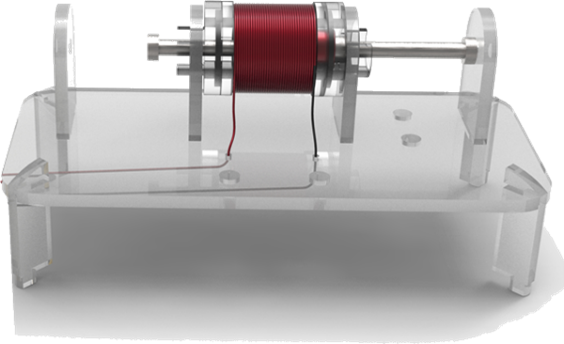
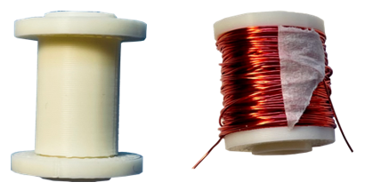
A solenoid is the heart of the linear motor (Figure 6). A solenoid consists of a tube with wire wrapped around it. The solenoid tube can be 3D printed, but the tube can also be formed from card stock. Insulated wire is wrapped around the tube to create a solenoid.
Figure 6
Solenoid Tube (left) and Wrapped Solenoid (right)
The wire can be wrapped around the tube by hand, or a mechanical winding device can be used. The rubber band winders (Figure 7) used to wind the rubber bands that power some model airplanes can be useful for this purpose. A counter in the winder can be used to maintain a count of the number of wraps. A 3D-printed adapter (available in the Educational CAD Model Repository) can be used to attach the solenoid tube to the winder (Figure 8).
Figure 7
Winder Used to Wrap Wire Around a Solenoid Tube
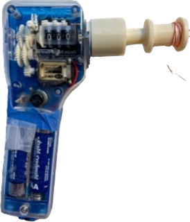
Figure 8
Close-Up View of Adapter Attached to Solenoid Tube

The solenoid and magnet are placed in a housing with armature rods on either side of the magnet. An external magnetic force can move the magnet inside the tube back and forth. End posts on either side of the housing prevent the magnet from falling out of the tube (Figure 9).
Figure 9
Enclosure for the Adjustable Linear Motor

Assembly consists of the following steps:
- Place the magnet and armature rods inside the solenoid tube.
- Add end plates to keep the components in place.
In most instances when we have engaged students at middle school grade level and above with these projects, they have not experienced difficulty in assembling the components.
Description of Use by Students in a Middle School Classroom
The linear motor kits were piloted in a seventh-grade Foundations of Engineering course at Buford Middle School in Charlottesville, Virginia. The prototype kit was successfully piloted with one section of the class with a dozen students. This unit was implemented during the course of three 40-minute periods and one 90-minute period. A sample lesson plan that details the structure of each class in the unit is available in the Educational CAD Model Repository.
The components for the kits were fabricated at the Haystack Mountain School for the Crafts FabLab in Deer Isle, Maine. The students in the Haystack FabLab participated in a pilot manufacturing apprentice program, receiving credit and experience for fabricating the parts. If a school has a makerspace and there is sufficient class time, students could also fabricate the parts themselves. When this is feasible, it facilitates modification and reinterpretation by students. Since parts can take up to several hours to print, we recommend that students start the printing process during a class period before the one in which the parts are needed.
In our pilot, before students began constructing their motors, we held a short discussion asking students, “What makes things move?” and “Describe what you already know about motors.” An assembled working linear motor was then shown to the students, and its principles of operation were demonstrated.
The students at Bufford Middle School in Virginia used kits fabricated by the Haystack students in Maine, working in groups of three to four students to construct a motor. The middle school students participated in a sequence of activities designed to demonstrate underlying principles of electricity and magnetism in relation to operation of an electric motor. They then incorporated the working motor into another mechanism, consisting of a mechanical drum machine that could be programmed using a rotary encoder.
The mechanical drum machine had been previously designed by a group of six middle school girls participating in a Summer Engineering Academy in the Make to Learn Lab at the University of Virginia. Two engineering students, one from Virginia Tech and one from Old Dominion University, served as consultants to support these middle school girls in the design process.
Sequence of Activities
The following sequence of activities was used to introduce the linear motor and related concepts.
1. Magnetic Motor
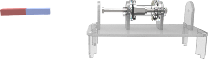
Students initially operate their motor manually by rotating an external permanent magnet. The external magnet caused the magnet inside the motor to move its armature back and forth (Figure 10). This step enables students to feel the attracting and repelling forces of the two magnets.
Figure 10
Using an External Permanent Magnet to Move the Armature of a Linear Motor
2. Rotating Magnetic Motor Controller
The students used a rotating wheel (fabrication files can be found in the Educational CAD Model Repository) with two permanent magnets mounted on the rim to move the armature of a linear motor back and forth. The mechanical mechanism consisting of a rotating wheel enabled students to increase the rate at which the linear motor moved back and forth (Figure 11).
Figure 11
Rotating Controller and Linear Motor
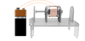
3. Manually Operated Electric Motor
The students then used a nine-volt battery powering a solenoid to move the armature of the linear motor back and forth (Figure 12). Students changed the polarity of the magnetic field generated by the solenoid by switching the leads to a battery to reverse the current, causing the armature to move back and forth. This sequence was designed to enable students to understand that the effect on the armature of the linear motor was the same, regardless of whether the external magnetic force was created by a permanent magnet or an electromagnet.
Figure 12
Manually Operated Electric Motor
4. Electronically Operated Electric Motor
Once students understood the foundational concepts through manual operation, an electronic oscillator and amplifier was used to operate the linear motor. The Adjustable Linear Motor was also introduced at this point in the sequence to broaden the design options available to students.
5. Incorporation Into a Mechanism
The sequence culminated with design of a mechanism incorporating a linear motor. This original design by the student demonstrates competency in understanding and use of a linear motor.
Extensions
After the main sequence of activities is completed, several options for extension activities allow for continued exploration of the linear motor. Students in the Buford Middle School class participated in an extension involving fabrication of manual controls to operate the motor. These activities are described in the following section.
Manual Control
After the seventh-grade students at Buford Middle School constructed linear motors, they used their linear motor to create mechanical drum machines. This extension involved development of a relay to control the motor.
1. Reed Switch
Students first designed and fabricated their own reed switch to gain an understanding of its operation. They then used the reed switch to control the operation of the linear motor (Figure 13). When a magnet was placed near the reed switch, the closing contact initiated a flow of current through the solenoid, causing the armature to move. The linear motor was mounted in a vertical orientation. Therefore, when the reed switch was opened, gravity pulled the armature of the motor downward.
Figure 13
Image of Reed Switch and Linear Motor

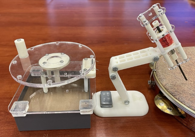
2. Programmable Magnetic Controller
A mechanically programable magnetic controller (Figure 14) was then created to operate the linear motor. The magnetic controller consisted of a disk with slots for magnets in the rim. When the disk rotated, magnets in the rim activated the reed switch, causing the armature of the linear motor to move.
Figure 14
Programmable Drum Machine
When the magnets in the rim of a rotating wheel activated the linear motor, it caused the armature of the motor to strike a percussion instrument. Students designed different types of percussive surfaces such as a metal bowl, a drumhead, and so forth, to produce different sound effects. They then programmed the rotating controller by repositioning magnets in the rim to create different drum patterns by changing the positions of the magnets on the rim. This activity was used as the introduction to exploration of rhythms in different cultures, including rhythms in European, Latin, Asian, and African cultures. A parallel activity in the educational programming language Snap! enabled students to reconstruct this activity in a digital environment.
Computer Control
Most contemporary linear motors are controlled by electronic devices rather than mechanical mechanisms. Due to time constraints, students in the pilot middle school class were not able to explore these activities. The middle school girls who participated in a Summer Engineering Academy were able to create computer-controlled mechanisms due to the additional time available (2 days per week for 4 hours per day during a 6-week period).
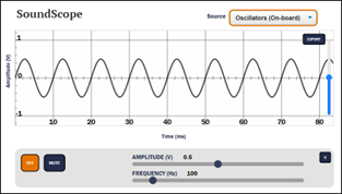
Once students in the Summer Engineering Academy mastered the basic principles of operating a linear motor using mechanical mechanisms, they used a computer-controlled oscillator to control the motor. A web-based tool, SoundScope, was created to control the linear motor. SoundScope (https://maketolearn.org/soundscope) is an audio frequency oscilloscope with oscillators developed in the Make to Learn Laboratory (Figure 15). SoundScope can be used to generate both pure tones and complex waveforms.
Figure 15
SoundScope Oscillators Used to Control the Linear Motor
The output of SoundScope oscillators was connected to the linear motor through the headphone jack of a laptop computer. The frequency of the oscillator controlled the rate at which the linear motor moved back and forth. A Dayton Audio DTA-1 amplifier was used to amplify the current and generate a magnetic field that moved the armature of the motor (Figure 16).
Figure 16
Dayton Audio DTA-1 Amplifier Connected to a Linear Motor

The Dayton Audio amplifier can be operated with either batteries or a power adapter, which is particularly convenient when a limited number of electrical outlets are available. (Note that some audio amplifiers have low-pass filters that reduce the amplitude of signals below the audible range of frequencies, i.e., below 60 cycles per second). Since the linear motor is designed to operate in the range of 1-20 cycles per second, an amplifier that can operate in this frequency range is required for effective use.
The use of SoundScope oscillators combined with an amplifier to drive the linear motor enables students to understand the relationship between a waveform such as a sine wave and movement of the linear motor. Each time the polarity of the waveform changes, the armature of the linear motor also reverses the direction in which it moves. This relationship can be readily observed at low frequencies (i.e., 10 Hz and lower).
Once students were successful in using an electric oscillator to drive a linear motor, this expertise was extended to control the linear motor with a computer program. TuneScope (Figure 17) is a tool that combines SoundScope with Snap!, an educational programming language developed at the University of California, Berkeley. The TuneScope library introduced in Snap! 8 includes commands that can be used to generate waveforms that control the linear motor. This method enables students to understand the way in which a microcontroller can be used to control a linear motor in industrial use with a minimum of technical overhead. This extension has now been incorporated as a library that can be accessed from within Snap! (Figure 18).
Figure 17
TuneScope Code Used to Control the Linear Motor

Figure 18
TuneScope Library in Snap! Block Programming Language

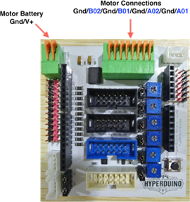
Some of the students also used an Arduino microcontroller to control the motor. The output of the Arduino analog connectors is not sufficiently powerful to drive the linear motor; therefore, an adapter with a motor controller (the Hyperduino 4-R adapter shown in Figure 19) was used to operate the motor.
Figure 19
Arduino Adapter with Motor Controller
The students used Snap4Arduino, an extension of Snap! that enables it to be used with microcontrollers. The addition of a microcontroller makes it possible to combine the linear motor with lights, sensors, and other actuators, making more complex projects feasible. The students were able to combine these concepts effectively to create their own designs that incorporated the linear motor.
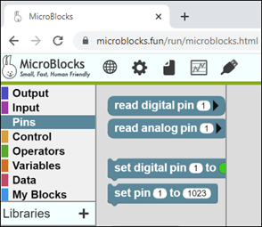
Another block programming language, MicroBlocks (https://microblocks.fun/run/microblocks.html; Figure 20), was also used to control the motor in a subsequent class. More detailed information on use of these applications in conjunction with linear motors is provided under the Instructional Materials section of the Linear Motor Kit in the Educational CAD Model Repository.
Figure 20
MicroBlocks
Revision and Remixing
In previous implementations of the Linear Motor Kit, students in middle school, high school, a community college technical class, and an undergraduate university maker class incorporated various versions of the linear motor into a wide range of mechanisms that they designed. For example, a leaping dolphin and a hot air balloon designed by students are shown in Figure 21.
Figure 21
Student-Designed Mechanisms That Incorporate Linear Motors

Depending on the age of students and the tools available, the mechanisms constructed can range from simple to complex. For example, students constructed a popcorn maker (Figure 22) using card stock and hand tools. The linear motor was placed in a vertical orientation beneath the popcorn platform, shaking the platform and causing the popcorn inside to move.
Figure 22
Popcorn Machine Constructed From Card Stock

The design in Figure 23 below was developed in Fablevisions’ Computer-aided Design (CAD) program for children, FabMaker Studio. It depicts a scene from the book The North Star (Reynolds, 2009).
Figure 23
Cardstock Mechanism Depicting a Scene From a Story

Math Extensions
After working with solenoids and building linear motors in class during the academic year, some middle students attended summer workshops that provided opportunities to extend their learning. One of the optional challenge tasks during one summer workshop asked students to relate the strength of the magnetic field produced by a solenoid (B) to the number of wraps of wire that comprise the solenoid (N), the length of the solenoid (L), and the electrical current (I). This relationship is known as Ampere’s Law,
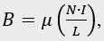
where is a constant. A set of calibrated solenoids was constructed for this challenge which was posed it as a sequence of four subtasks, relating magnetic strength to solenoid length, to number of wraps of wire, to current, and finally to the combination of these variables taken together. Students, working in groups of threes, were able to successfully determine that for the set of solenoids they tested was:
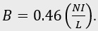
See Corum and Garofalo (2018) for details.
In a different summer workshop, middle school students built electric instruments and used solenoids to make pickups. In one case, students were challenged to determine where to place frets on a fret board so that their instrument intonated properly. A sequence of three tasks were developed to facilitate this challenge. And, although these students had no prior exposure to fractional exponents beyond square and cube roots, they deduced, by detecting and generalizing a pattern, that the solution to this challenge required division by

See Garofalo et al. (2022) for details.
Student Outcomes
For the most current pilot in Foundations of Engineering course at Buford Middle School, the design team was unable to identify a standardized test that covers this material. The team, therefore, developed a series of short-answer questions designed to assess student understanding (also available in the Educational CAD Model Repository).
Student understanding of this invention can encompass several types of knowledge including technical discussion (what the inventor did), social context (the era in which the inventor worked) and cultural impact (the way in which the invention changed the world).
Middle school students completed assessments of electricity and magnetism concepts in one implementation. On a pretest, fewer than 20% demonstrated understanding of these concepts and exhibited a variety of misconceptions. On the posttests, most students demonstrated an understanding of electromagnetism, with answers ranging from 67% to 93% correct (Standish, 2017). Students made significant gains (p < .05) related to electricity and magnetism concepts.
During the sequence of linear motor activities, students also learn practical as well as theoretical skills, including development of troubleshooting and debugging skills when the linear motor was not functioning properly. The length of the armature rods attached to the permanent magnet inside the solenoid is critical to ensure that movement of the magnet falls within the area of greatest magnetic force generated by the solenoid. The ends of the armature rods must also lie flush with the ends of the cylindrical magnet to ensure proper movement. Ensuring reliable movement of the motor requires attention to detail as well as theoretical knowledge. The troubleshooting process provides opportunities for collaboration across groups as factors related to reliable operation are identified.
Discussion
The Linear Motor Invention Kit evolved from a strand held at the 2014 National Technology Leadership Summit. Members of an advisory board met to develop recommendations for a design for an electric motor kit that could be used in middle school science and engineering courses. The advisory board included representatives from the National Academy of Engineering, the National Council of Teachers of Mathematics, the National Science Teachers Association, the International Technology and Engineering Education Association, and editors of related journals in those fields. A subsequent workshop convened a group of middle school science teachers.
The linear motor kit has proven successful for introduction of the underlying concepts in a variety of grade levels and settings. The following year at the 2015 National Technology Leadership Summit, a group of seventh-grade students from Buford Middle School met with the advisory board from the year before. Each member of the advisory board was assigned a seventh-grade coach to assist them. With the support of their seventh-grade assistants, each member of the advisory board was able to design and construct a working electric motor successfully.
The Linear Motor Kit described in this manuscript is the descendent of that design. The middle school students were all able to create their own mechanisms using the linear motor successfully. They were able to answer assessment questions that address the effect of one permanent magnet on a second permanent magnet. They were less successful in responding to questions related to the effect of an electromagnet on a permanent magnet. Additional scaffolding regarding the nature of electromagnets could potentially result in improved understanding in future implementations.
The success students enjoyed at both the middle school and undergraduate levels suggests that a linear motor can be a successful introduction to concepts of electricity and magnetism, either as a precursor to the introduction of rotary motors or as a standalone culminating activity.
References
Bull, G., Chiu, J., Berry, R., Lipson, H., & Xie, C. (2014). Advancing children’s engineering through desktop manufacturing. In J. Spector, M. Merrill, J. Elen, & M. Bishop (Eds.), Handbook of research on educational communications and technology (4th ed.; pp. 1–105). Springer.
Bull, G., Haj-Hariri, H., Atkins, R., & Moran, P. (2015). An educational framework for digital manufacturing in schools. Journal of 3D Printing and Additive Manufacturing, 2(2), 42-49. https://doi.org/10.1089/3dp.2015.0009
Bull, G., Standish, N., Johnson, E., & Haj-Hariri, H. (2016). Educational leadership and planning for digital manufacturing in schools. In R. Huang, Kinshuk, & J. K. Price (Eds.), ICT in education in global context (pp. 173-194). Springer-Verlag
Bull, G., Garofalo, J., Littman, M. & Hoffman, M. (2018). The Make to Learn electric motor design sequence. International Journal of Designs for Learning, 9(1), 1-13.
Corum, K., & Garofalo, J. (2018, October). Analyzing 3D-printed artifacts to develop mathematical modeling strategies. Technology and Engineering Teacher, 78(2), 14-20.
Corum, K., & Garofalo, J. (2019). Engaging preservice secondary mathematics teachers in authentic mathematical modeling: Deriving Ampere’s Law. Mathematics Teacher Educator, 18(1), 76-91.
Garofalo, J., Corum, K., & Rutter, J. (2022). Engineering as a context for learning mathematics: The case of guitar fret spacing. Technology and Engineering Teacher, 82 (2), 14-18.
International Technology and Engineering Educators Association. (2020). Standards for technological and engineering literacy: The role of technology and engineering in STEM education. https://www.iteea.org/STEL.aspx
National Governors Association Center for Best Practices & Council of Chief State School Officers. (2010). Common core state standards. Authors.
National Museum of American History Mission and History. (n.d.). Mission & history. http://americanhistory.si.edu/museum/mission-history
NGSS Lead States. (2013). Next generation science standards: For states, by states. The National Academies Press.
Reynolds, P. (1997). The North Star. Fablevision Press.
Standish, N.R. (2017). FabNet invention kits: Outcomes and implementation [Doctoral dissertation, University of Virginia]. LibraETD. https://libraetd.lib.virginia.edu/public_view/dj52w4777
![]()